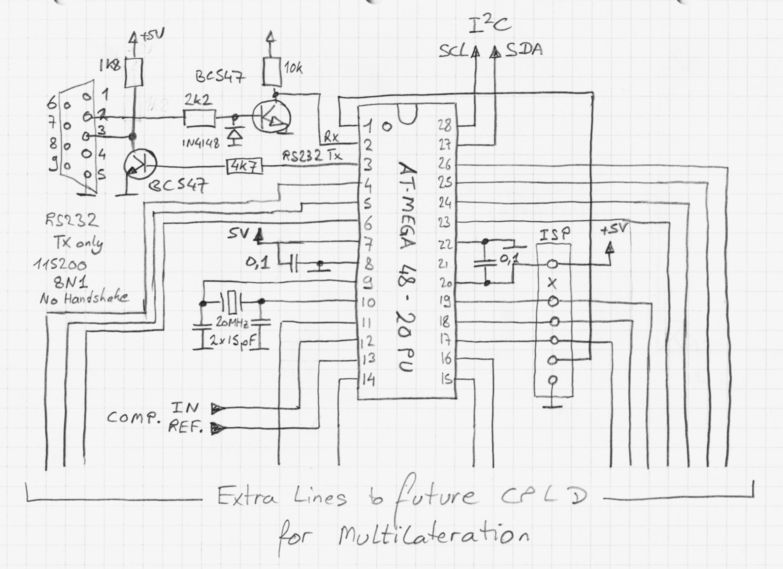
Some of the microprocessor I/O lines can be used for configuration and
for signaling (LEDs, etc). Other I/O lines could be used for
multilateration using a CPLD (i.e. XC9572 from Xilinx. I am still
working on a circuit board layout. Due to the simpleness of the circuit
the layout could be single sided including the future socket for the
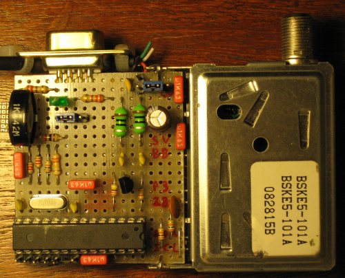
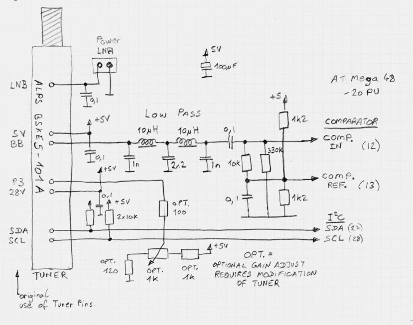
CPLD. Current pin 6 of the microcontroller goes to a green LED
connected to GND via 330 Ohms to indicat a valid frame received. This
may change depending on the final layout with the optional CPLD.
The program is 100% assembler and is written for the Atmel AVR Studio
which is available for free on the Atmel web site. It sets up the
serial line speed, configures the analog comparator. The main loop
waits for a valid sync pattern and then decodes the manchester encoded
ADSB frame. If a manchester encoder bit is corrupted the decoding is
aborted. When a full frame is correctly received, the result is sent in
Hex to the serial line and the loop starts again. During the serial
line transmission no frames are received. Anyway it is not important to
receive all frames in order to watch the planes on the monitor screen!
Download the
ASM Source file
for use with the free Atmel AVR Studio. Assemble for a ATmega48-20
target. Atmega48 Fuses must be set for External Fast Quarz Oscillator
and Clockoption must be off for maximum speed of the microprocessor.
The output would look like this:
*8D75805B9944F033C0045DA67C63;
*8D75805B58C392AC308A95C63185;
*8D75805B58C392AC7A8A80C6EFBA;
*8D75805B9944F033C0045E599471;
*8D75805B9944EF33C8045E16F883;
*8D75805B200C50B9DB6820B0ED78;
*8D75805B9944EF33C8045E16F883;
*8D75805B58C392AED889D234AC39;
*8D75805B9944EF33C0045E785A8B;
A star is a start of frame indicator, 112 bits frame follows in Hex and
is terminated with a semi colon. These frames where received from air
frame
75805B here in
Cebu. This can be looked up on
Airframes
database and one can see it to be registration RP-C3195 which is an
Airbus A-319-111 belonging to Cebu Pacific Air.
More info on ADSB and how the frames are constructed can be found on
Radar Basics
especially the chapter on
Downlink
Broadcast and many other sites.
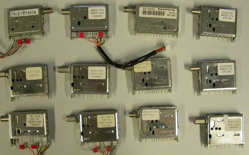
Other sources for the ALPS tuner:
albs Alltronic LagerlisteOther maybe possible tuners:
Modulo tuner decoder SATFurther tuner info:
DJ6IY Pinbelegung einiger analoger SAT-Tuner
Decoding the framesTo decode ADSB there are two main documents you will need to study.
The first document is:
ICAO:
Annex 10 to the Convention on International Civil Aviation, Volume IV:
Surveillance and Collision Avoidance Systems. Latest I could find was
Fourth Edtion July 2007.This document describes how Mode
S works, the different formats, and how the extended squitter is
encoded and transmitted at 1090 MHz. If you look hard you can find an
old PDF version of this document on a danish web site (sorry I'll say
no more).
and the second document is:
ICAO:
DOC 9871 (AN/464) Technical Provisions for Mode S Services and Extended
Squitter. This is a fairly new document, First Edition - 2008, and I
think it has replaced the famous DO-260A.This
goes into the nitty gritty and ugly details of the strange beast that
is an ADSB broadcast. I had to realy get my teeth into this document.
I'm afraid you have to pay for this one. Bits and pieces about decoding
the famous CPR (Compact Position Reporting) frame can however be found throughout the internet as
it's encoding and reliability was subject to much debate and some
misunderstandings and about 30 bits and pieces can be found on the web.
Together they give a good idea of what is going on.
Usefull things to look for are:
ADS-B for Dummies
Transition Table for NL(lat) Function
Technical Standard Order TSO-C166
Proposed Change for Global Decoding of the ES Surface Format
CRC Calculation for Mode-S Transponders
and go from there ...
As many e-mails ask me "how is it done?" I have made
a small article on how to decode CPR frames.
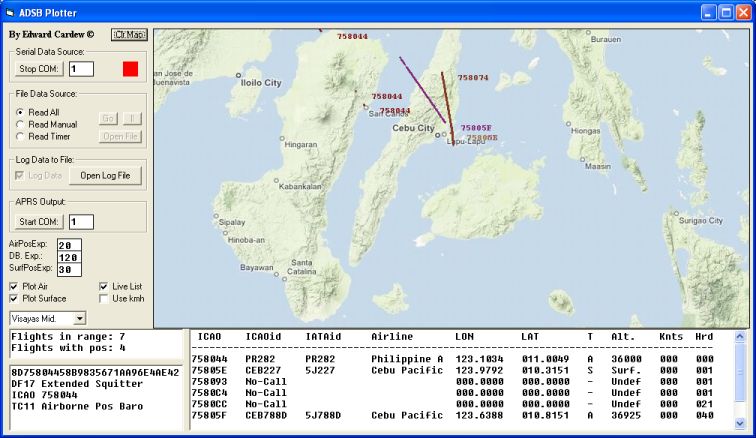
The SoftwareCurrently
only a basic software has been written for Microsoft Visual Basic 6
(sorry Linux guys, but I just wanted to plough ahead with what I knew).
It
is still buggy and some features are just empty buttons but in Europe
and the Philippines, it works. When planes jump accross "NL" boundries,
the coordinates go wrong for several received frames until it syncs to
the next "NL" box.
Type the COM port number into the text box and click start. Different Maps are defined in the
setup.txt file.
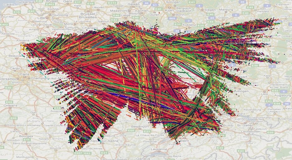
The frames should apear like
this video on the bottom left of the application.
Download the new version with maps (sorry for old file without maps) which is
Version 10.
Any feedback on the software or hardware are very welcome, my email is on my
main page.
Please
be aware the software is very dirty and only written to test the
hardware. A setup file tells the program what maps are available. The
program has still many errors and many parts that do not work or are
incomplete or disabled. Like I said ...
The setupfile starts
with a single line which tells how many entries there are. The maps are
described one at a time, one per line as follows:
"Map Name", "Map
location.jpg",MapX,MapXsize,MapY,MapYsize,Size Of Dot during
Plotting,Line Width during Plotting,Correction factor for Surface
Positions
AirPosExp sets the expiry time (sec) for an airborne position.
DB Exp sets the time for an airplane to leave the database.
SurfPosExp sets the time for a surface position to stay valid.
You can also open a previous log (logged with a terminal software) and play the file.
Live
List disables the update of the database window making the software
much faster and enabling a cut and paste from the window.
As I said many things are incomplete such as kmh, etc ...
I hope some people out there decide to make a nicer interface as software is not my forte!
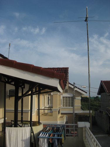
My Setup in Cebu, PhilippinesMy
outside antenna is a Jpole tuned to 1090 MHz and a broadband preamp
based on a BFP420. It is housed in a piece of gray PVC pipe and a
yogurt pot on top. The cable run is about 25 meters. It is placed above
the TV aerial to the side of our terrace.
Test #2 with SF1218C-MK2This
is the second tuner I got to work. With a nice aerial and a preamp I
get ranges over 200km radius. With a piece of wire I get about 25km
from a high vantage point. Minimum attenuator at input to get FM
decoder working is 6 dB. See pictures ...
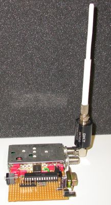
The SF1218C-MK2 receiver with a 6dB attenuator and a piece of co-ax open on one end by 6 cm.
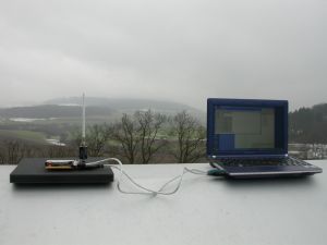
The device in test. Range: ca 25 km!
Links to other pages covering ADSB, Mode S and SSRA simple ADS-B Decoder by Bertrand Velle.This
Decoder goes along a similar route as my previous receivers but uses a
PIC. Also Bertrand is analyzing more than just the DF17 ADS-B messages
but also for example the TIS-B messages.
ADS-B and APRS projects by Andrew Rich.Andrew
has been doing work on ADS-B for a long time. A very interesting
website, including ADS-B to APRS and captures of mode S frames as
received on Andrew's SBS1 receiver.
G4FEV HomeMade ADS-B receiver by Dave.A mix of his own and Bertrand's efforts. Nice cavity filter and simple homebrew RF frontend.
The miniADSB - 1090 MHz - Receiver Project.A pure open-source hardware project.
1090 MHz-ADS-B-Receiver by vinculum.The
mikrocontroller.net forum is an excellent but mostly German forum. ADS-B is a regular topic there.
3
Other Tread with this Project.
For the antennaLink to my BFP420 preamp.Link to my J-pole antenna.Access to this page is counted out of curiosity ;-)