Overview
Outdoor Configuration
Indoor Configuration
Measurements
Prototype Number 2
Changes, Notes and Docs
Links and other stuff
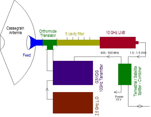
I don't know where to start on this one as it is still many single bits and bobs floating around that are still lacking other bits to bring the whole thing together. The idea that has emerged so far is to use an Ethernet card with a 10BaseT connection (kept short) to a modem which converts the signal to BPSK. For the moment no synchronization is done, and the whole Manchester encoded data with the link pulse is modulated to 480 MHz band using BPSK. The receiver is to be a simple 70 MHz BPSK demodulator regaining the carrier with a frequency doubler. Receive IF is therefor 70 MHz with 40 MHz bandwidth using a converted LNB (more on this later). A UHF / VHF splitterb combiner ensures that a single coax cable can be used to connect the RF link part to the modem. The RF link is currently a 45 cm Cassegrain antenna. A feed with OMT splits horizontal and vertical signals. The transmitter is a 10 GHz G3WDG003 upconverter by Petra Suckling G4KGC and Charles Suckling G3WDG (find out more here). I have built two of these and each one produces more than 70 mW. The receive LNB has a home built 5 cavity filter in front of it to get rid of the transmit signal. Again a cheap satellite / terrestrial diplexer splits the signals and extracts the DC needed. Transmission and reception would be done in the 10 GHz band at 10.080 GHz and 10.480 GHz. The filter at the LNB side must therefor select one of these sub-bands and attenuate the other by at least 80 dB otherwise the LNB goes into compression an the receive signal is lost.
Note for the sceptics:10BaseT over radio works, I have done it, but so far only at 70 MHz. The rest is just frequency conversion ...
The following diagram shows the outdoor configuration:
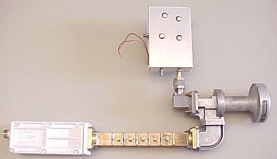
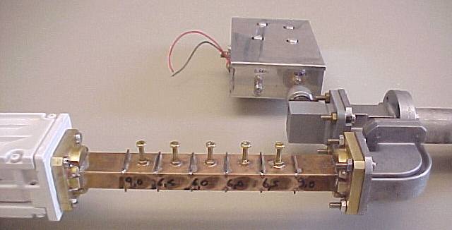
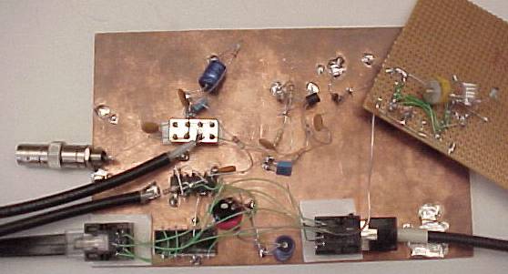
And the picture below shows how far I have got:
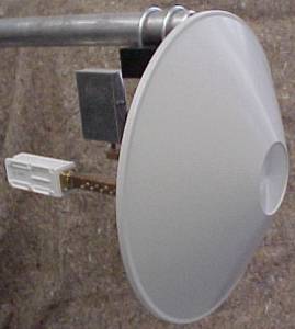
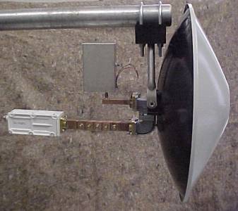
With the dish ...
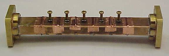
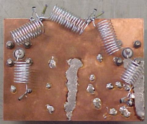
A closeup of the old 5 cavity filter shows the iris size markings:
A previous version of the cavity filter with 3 cavities which does not provide enough isolation from the transmitter:
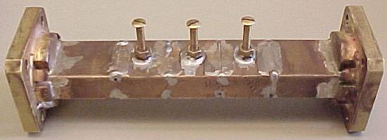
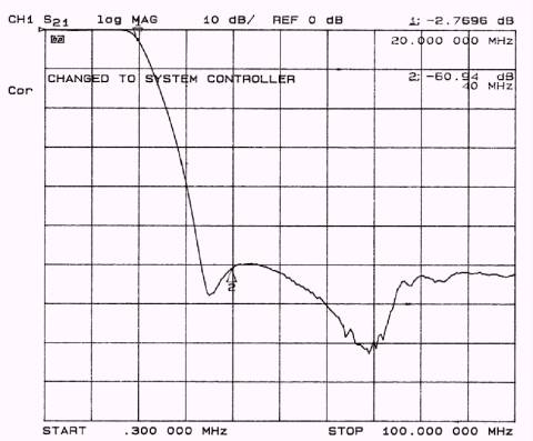
This filter has well over the wanted 80 dB at more than 300 MHz, a 3 dB bandwidth of 55 MHz and the through loss is not super but better than 10 dB:
10BaseT signals are received with a standard Isolation Transformer with built in filter. These are very common on PC cards but can be difficult to find in single quantities. Try to get some samples from a distributor (Invent a story ...). The other side of the transformer is biased so that the inverter gate can take over. This signal then passes several gates at once to be buffered. The recovered 10BaseT signal from the logic converter is passed trough a 5 pole filter with the following measured characteristic:
The new prototype #2 demodulator has been measured with the following BER:
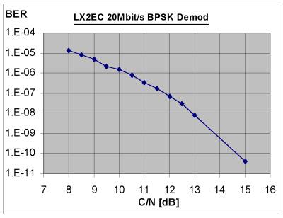
As my current link budget is for S/N=20dB, I see no problem with TCP/IP over such a link!
Prototype #2 has a seperate modulator and demodulator. It uses a low frequency LNB origianly an old Technisat 10GHz Lo LNB:
Before modification:
This is what the L-band amplifier looked like before modification:
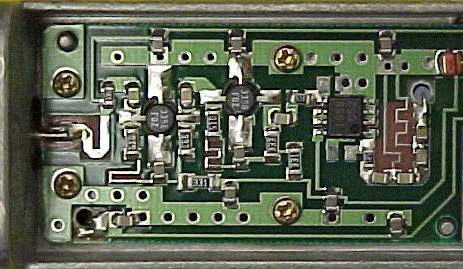
After the simple modification:
Measured gain at 10.07 GHz is over 55 dB and the noise figure is better than 2 dB.
The modulator is pretty much a finished design:
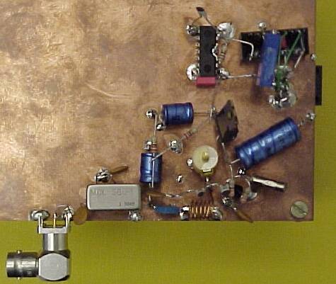
The ethernet connection and the low pass filter described above are on the underside of the board. the top right part of the board has the ethernet - TTL - 50Ohm converter. The signal passes through the board to the filter. On the bottom right is the 70 MHz oscillator which feeds the SBL-1 mixer. The resulting BPSK signal finishes up on the BNC connector.
Modifications of this design will be a local oscillator at 480 MHz from a 24 MHz Crystal running at 120 MHz and going through two doublers to give 480 MHz. At this frequency readily available Satellite IF filters can be used to clean up the output spectrum.
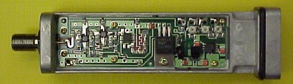
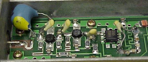
The demodulator works well but requires an input signal between 0 and 5 dBm:
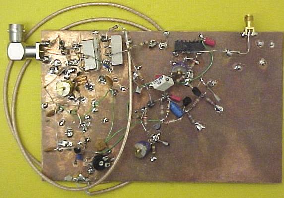
The signal starts at the top left, passes through a first SBL-1 mixer which doubles the frequency and stores the signal in the resonant tank below. After further amplification the signal passes into the 74AC74 divider (SMD version below the trim-pot). The 70 MHz coherent carrier is shifted by 90 degrees through the coax and ends up at the top of the board in the second SBL-1 mixer which returns the baseband signal from the original BPSK signal. The baseband signal is amplified via a 4 transistor DC amplifier and converted to TTL on the top right.
I am thinking of using a 2m / 70cm diplexer instead of the Satellite / Terrestrial splitter.
Docs
E2010 Ethernet 10BaseT Transformer.
N6GN's Higher Speed
Packet Page.