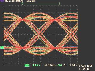
I will not yet include the modulator here yet as it is straight forward and uses an EPROM table with 16 x over sampling to make I and Q signals. The eye diagram of the modulator looks something like this:
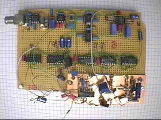
Demodulator Prototype
The demodulator has a NE612 input mixer which currently mixes a 6.30MHz ADR carrier to 10.7 MHz IF. Then it passes through a standard 10.7 SAW filter of the cheapest sort. A MC1350 TV IF amplifier provides gain as required by the AGC voltage. The output of which passes to two NE612 mixers which mix their respective input signals to I and Q signals using 0° and 90° local oscillator signals running at 10.7 MHz. I and Q signals are amplified and then go to different circuits. One circuit rectifies one of the signals and via a threshold detector and some smoothing produces the AGC voltage which drives the MC1350. On a separate circuit the I and Q signals are converted to TTL signals defined as I, Q, I + Q and I - Q using a LM339 voltage comparator. These four signals are mixed together with EXOR gates to produce I x Q x ( I + Q ) x ( I - Q ). This equates to I x Q x ( I2 - Q2 ). When locked I2 and Q2 are equal to 1 and therefor cancel out, this is how the phase is locked, be it with the usual 90° ambiguity. The "Costas Loop" error signal is integrated and feeds a 42.8MHz VCO. Using latches and EXOR gates this signal is divided into the 0° and 90° local oscillator.
Power supply is currently 15 Volts (And I plan to make that 15 Volts only!)
It is important to me that the whole circuit does not use a single thing that is not available in single quantities via your local electronics dealer. The worst candidate for that statement is the FEC chip, but there is hope: The Qualcomm successor to the Q0256, named the Q1900 should be available in single quantities (assures the German representative) at about 25 Euros (where is the "euroglyph" in html???).
Schematics of prototype
QPSK Demodulator
RF input stage
The ASTRA base band signal at 6.30 MHz is fed to a mixer to convert the signal to 10.7 MHz IF. This stage may be changed at a later date to a fixed frequency. After that the signal is filtered with a standard FM SAW Filter from Murata (commonly available) and then fed to a Motorola TV IF amplifier IC. The output stage is tuned to 10.7 MHz can be aligned with a scope by blocking the AGC and by maximizing the I / Q signals. The I and Q signal come out of the quadrature mixer.
Quadrature mixer
The 10.7 MHz IF signal is fed to two NE612 mixers running with 0° and 90° local oscillators at 10.7 MHz. The resulting signals are I and Q but without any further help they would still contain a frequency and a phase offset, these need to be locked out using the Costas Loop.
Costas Loop
I and Q signals are digitized to I, Q, I + Q and Q - I . These are then EXORed together to form I x Q x ( I + Q ) x ( Q - I ) and then integrated. The VCO control voltage is kept to a short voltage swing which can be adjusted so that the VCO voltage is 7.5 Volts when locked on the exact center frequency. The Costas Control input goes to a Tri-State output of the microcontroller. This simple method allows the microcontroller to scan for phase / frequency lock.
VCO
Pretty simple this one, take care with the RF part (no microphonics and other unwanted stuff), shielded TOKO coil, you get the gist. Latches provide the exact 90° phase shift.
AGC
I know, I know, the above is a horrible circuit but it works! Settling time of the AGC is a few seconds.
That is as far as I have got (04 Jan. 99).
HELP WANTED:
If anyone out there would like to help I need ideas for the following:
A reasonable Low Pass Filter to be used as I / Q filter with say 4 opamps, a steep cutoff and a linear phase all the way up to the cutoff.A PLL that will lock to a very jittery data signal, provide frequency and phase lock for triggering the ADC that will be used for the soft-decission with Viterby.